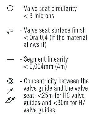
OEM subcontractors, high-performance specialists and engine rebuilders must take into account and respect precise shape and dimension tolerances while machining valve guides and valve seats.
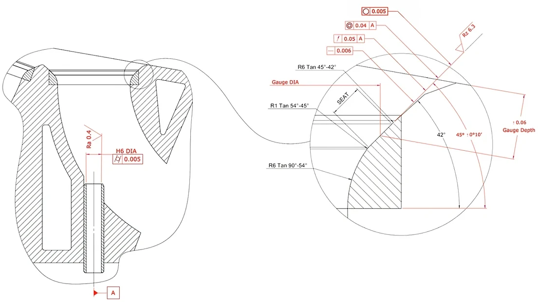
With this “aide-memoire”, NEWEN attempts to gather, within a short document meant for production technicians, the various symbols and tolerance signs typically used by OEMs to define their requirements in terms of cylinder head machining and, in particular, valve guide and valve seat machining.
NEWEN brings together each form and dimension tolerance with direct and indirect incidences on the functioning and reliability of the cylinder head, without attempting to over simplify or denature the combined effects of two or more parameters.
With this document, NEWEN is working on denouncing generally accepted ideas as well as false ideas, widespread ideas that, because of their simplism and inaccuracies, mislead engine rebuilders and alter their judgement.
« When you can measure what you are speaking about and express it in numbers, you know something about it; but when you cannot measure it or express it in numbers, your knowledge is of a meagre and unsatisfactory kind.»
Lord KELVIN (1824-1907)
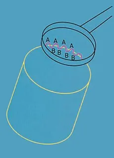
Why measure roundness?
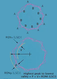
The component may appear round to the eye and apparently have a constant diameter when measured with a vernier or micrometer, but is it round? It is clear that the lobing can affect the function. Lobes at ‘A’ will carry the load whilst the lubrification film will be greatest at ‘B’.
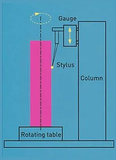
How is roundness measured ?
To measure roundness, rotation is necessary, coupled with the ability to measure change in radius. This is best achieved by comparing the profile of the component under test to a circular datum. The component is rotated on a highly accurate spindle which provides the circular datum. The axis of the component is aligned with the axis of the spindle, usually using a centering and leveling table. A transducer is then used to measure radial variations of the component with respect to the spindle axis.
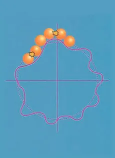
The reason ?
The bearing shown here could have a race that is not truly circular. This would probably function for a short time but the undulations around this bearing race would start to cause vibrations. This would result in premature wear and cause the race to perform less efficiently than intended.
Results ?
The bearing shown here could have a race that is not truly circular. This would probably function for a short time but the undulations around this bearing race would start to cause vibrations. This would result in premature wear and cause the race to perform less efficiently than intended.
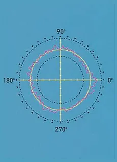
It is convenient to represent the out-of-roundness output from the gauge as a polar profile or graph. Evaluating this pictorial representation can be subjective and time consuming, therefore we need some means of processing the information to give us accurate and repeatable answers. As we are trying to assess departures from true circularity and require a reference from which to measure, it makes sense to try to fit a reference circle to our profile and relate all our calculations to it.
The Least Squares Reference Circle (LSCI)
A line or figure is fitted to any data such that the sum of the squares of the departure of the data from that line or figure is a minimum. This is also the line that divides the profile into equal minimum areas.
The LSCI is the most commonly used Reference Circle. The out-of-roundness is then expressed in terms of the maximum departure of the profile from the LSCI. i.e. the highest peak to lowest valley.
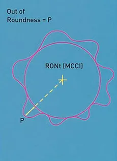
The Minimum Circumscribed Circle (MCCI)
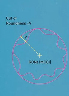
Defined as the circle of minimum radius which will enclose the profile data. The out-of-roundness is then given as the maximum departure (or valley) of the profile from this circle. Sometimes referred to as the Ring Gauge Reference Circle.
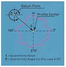
 = Eccentricity (ECC)*
This is the term used to describe the position of the center of a profile relative to some datum point. It is a vector quantity in that it has magnitude and direction. The magnitude of the eccentricity is expressed simply as the distance between the profile center and the datum point. The direction is expressed as an angle from the datum point.
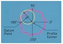
 = Concentricity (CONC)*
This is similar to eccentricity but has only a magnitude and no direction. The concentricity is defined as the diameter of the circle described by the profile center when rotated about the datum point. It can be seen that the concentricity value is twice the magnitude of the eccentricity.
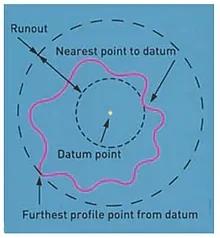
 = Runout (Runout)*
Sometimes referred to as TIR (Total Indicated Reading). Runout is defined as the radial separation of two concentric circles centered on the datum point and drawn such that one coincides with the nearest and the other coincides with the farthest point on the profile.
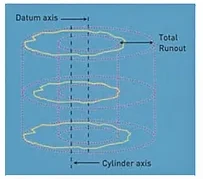
 = Total Runout (Total Runout)*
Total Runout is defined as the minimum radial separation of two co-axial cylinders, which are co-axial with a datum axis and which totally enclose the measured surface.
 = Flatness (FLTt)*
A reference plane is fitted and flatness calculated as the peak to valley departure from that plane. Either LS or MZ n be used
 = Squareness (SQR)*
Having defined an axis, the squareness value is the minimum axial separation of two parallel planes normal to the reference axis and which totally enclose the reference plane. Either LS or MZ can be used.
 = Cylindricity (CYLt)*
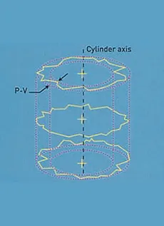
The minimum radial separation of 2 cylinders, coaxial with the fitted reference axis, which totally enclose the measured data. Either LS, MZ, MC or Ml cylinders can be used.
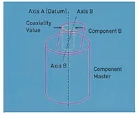
 = Coaxiality (Coax ISO)*
The diameter of a cylinder that is coaxial with the datum
axis and will just enclose the axis of the cylinder referred
for coaxiality evaluation.
 = Coaxiality (Coax DIN)*
The diameter of a cylinder that is coaxial with the datum axis and will just enclose the centoids (LS centers) of the planes from which the axis of the cylinder referred for coaxiality evaluation is calculated.
The function of the “trio” valve guide, valve seat and valve is to create a perfect, endlessly renewed and reliable air-tightness of the gaseous flux of the engine.
A metallic contact between two surfaces must constitute a reliable and airtight passage after hundreds of millions of consecutive opening and closing of the valves.
The two surfaces in contact, i.e. the valve seat surface of the valve and that of the actual seat itself, must have similar qualities and must be close to perfection.
The shapes of the above mentioned surfaces must be perfectly identical and completely complementary.
The only shape achievable with precision and in a repetitive manner, to fulfil this function, is the circle.
Associated with other parameters, the circularity, i.e. the accuracy of the shape of the circles constituted by the valve seat and the valve itself, turns out to be the main and sine qua none condition to a good air-tightness between the valve and the valve seat.
Circularity, cylindricity, surface finish, angles are all subjected to stricter and stricter tolerances.
Valve guide
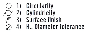
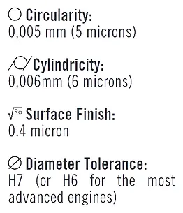
The valve guide is the reference, of which depends the positioning of the repair machining operation of the valve seat, of the control of part of the conformity of the valve seat (concentricity) and, of course, it guides the valve in its movements.The quality of a valve guide is essentially defined by 4 parameters:
To ensure a perfect guiding of the valve, cylindricity and the tolerance on the diameter are critical. Good geometric qualities will allow the valve guide to position the valve with precision overa long life time.
An important defect in the guiding of the valve, further to a poor machining of a valve guide – outside of tolerances, will lead to premature deformation and wear of the valve seat and a fast loss in engine output.
The tolerances commonly required by OEMs for current engines are:
The above tolerances, difficult to obtain and respect by large series manufacturers, are even more complex to guaranty when repairing. Failure to meet these quality levels will make the machining of the valve seats even more delicate.
Valve Seats and Valves
In view of the importance of the precision of the surfaces that will be in contact and that, because of their complementarity, will ensure a perfect airtightness, OEMs tighten shape tolerances of the seat tapers .
The linearity of the seat angle segment and its circularity are toleranced with value differences not exceeding a few microns (< 10 microns). Ra and Rz values defining the surface finish of the valve seat and also very tight and the smallest chatter mark or undulation of the seat, yield a seat that is out of tolerance and unacceptable.
The tolerances applied to the notion of concentricity, runout or double runout between the axis of the valve guide and the axis of the valve seat also are very important yet remain within values relatively easy to guaranty.
Generally, concentricity defect/runout in the order of 0.05mm (.002”) is considered acceptable. All these tolerance values are seriously tightened with the application of a coefficient called “Cpk” issued out of the rules applicable to companies certified ISO/TS16949 and reduces considerably tolerance values through the use of machines capable of guarantying great consistency in quality.
This approach having for objective to guaranty quality is made possible since human error is avoided as much as possible owing to the use of numerical systems triggering and controlling mechanisms yielding always more performance.
NEWEN FIXED-TURNING® comes within the logic of the evolved and high-performance mechanical principle, piloted and controlled with a unique high performance numerical control.
The FIXED-TURNING® provides and guarantees:
This level of quality is the highest today and is accessible to all people machining valve seats, from the smallest engine rebuilder to the largest production facilities using NEWEN FIXED-TURNING®.
Lastly, NEWEN FIXED-TURNING® is a reliable and consistent production means, economical and flexible, allowing to take into account the most severe Cpk while controlling one’s profits.
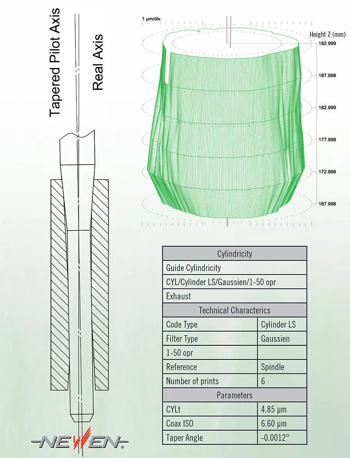
The demand for constant quality (Cpk) and precision for new cylinder head production, highlights the inadequacy of the principle of the tapered pilot as an acceptable solution for valve seat machining.
This solution, long appreciated for its economical aspect, no longer responds to current technical requirements.
The axis/position taken by a tapered pilot within a valve guide is never the same than the one that would be determined by measurement and/or that taken by a valve while in movement (refer to drawing).
This difference is further accentuated by the shape defect of a new or used valve guide (please refer to the graphical representation of a new valve guide by a Talyrond measuring machine)
The random positioning of the pilot within the valve guide goes against the notion of Cpk so developed today within all OEMs.
Without forgetting that even in the case of a simple repair, the very dimension of the pilots required for current engines is not sufficient, in any case, to resist to the irregular cutting efforts of form tools.
NEWEN refutes energically the position of the defenders of this obsolete technique.
Likewise, the form tool exhibits too long a cutting profile to guaranty a regular cut over 360 degrees (evenly around the seat).
The value of the inside relief can vary on a scale of 1 to 3 on one same seat and the radial efforts absorbed by the spindle will inevitably trigger the actual flexing of that latter and will translate into a form defect of the valve seat such as chatter marks, undulations and/or oval forms that will make the machining of the seat incorrect and out of tolerance.
Current valve seat materials and required tolerances are no longer compatible with this machining technique.
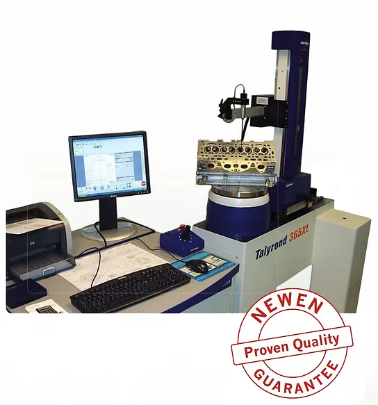
Traditional measuring means are not sufficient to precisely control valve seats and valve guides machined with NEWEN® FIXED-TURNING® machines.
NEWEN® has equipped itself with a TALYROND 365XL control machine, especially conceived and dedicated to the measurement of shapes, coaxialities, surface finish...
This machine whose resolution is 1/100 of a micron allows to automatically control all geometric parameters that define the quality of a guide and a of valve seat: circularity, concentricity, run out, cylindricity, segment linearity, angles, surface finish... The control reports and graphs resulting from the tests are indisputably recognized by the control departments of the most prestigious OEMs.
NEWEN is continuously testing the work produced by the machines it manufactures and demonstrates quality with actual measures.
Like the principle of a CNC lathe, FIXED-TURNING ® is the machining of valve seats and/or any revolution shape by interpolation of axes.
Aside from the fact that it is the cutting tool that is spinning and not the part being machined itself, the machine spindle and machining head allow to very simply machine the most difficult and most complex shapes regardless of the quality of the valve seat material. While rotating, the cutting tool moves on its x and z axes to describe the profile to machine. The machining is performed in one direction and the number of passes is automatically defined by the program itself. The travel of the cutting tool is optimized according to the actual shape of the raw valve seat. A standard triangular cutter moves according to the axis of the carriage and the axis of displacement of the spindle. The whole rotates around the C-axis.
A powerful computer permanently calculates the optimal trajectory of the tool so that the cutting efforts are regular and reduced to a minimum. Every single shaving calculated from a fraction of a second to a fraction of a second is produced in such way that no fluctuation of the cutting efforts disrupts the balance and the flexibility of the spindle.
Thanks to FIXED-TURNING ®, perfect valve seat machining and a perfect seal between the valve seat and its valve are attained each and every time, the first time, without lapping.
Modern controls, latest technology, efficient, simple, extremely user friendly, relieves the operator of repetitive gestures, reduces fatigue and frees up attention for essential operations.
The interaction with the machine is user friendly and simple. The operator only needs to enter familiar dimensions such as the diameter of the valve, select a profile and the machine will instantaneously calculate everything else, including all roughing and finishing machining passes.
Beyond precision, beyond mere user friendliness and added productivity, FIXED-TURNING ® is the equivalent of thousands of custom form tools, all permanently packaged in one simple and affordable machine.
Long Live Engine Rebuilding.

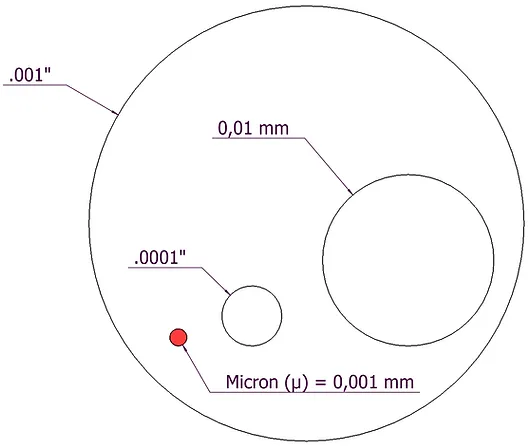
 = Eccentricity (ECC)*
 = Concentricity (CONC)*
 = Runout (Runout)*
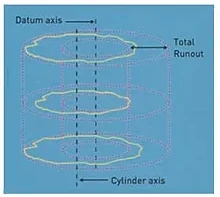
 = Total Runout (Total Runout)*
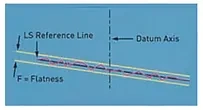
 = Flatness (FLTt)*
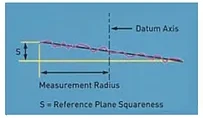
 = Squareness (SQR)*
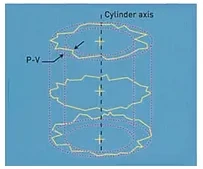
 = Cylindricity (CYLt)*
